To view our guide on which hydraulic pump is right for your application, click here.
The Hydraulic Pump is a key component of every hydraulic system; it converts the mechanical energy of a motor (prime mover) into hydraulic energy. The pump is the component of the system that ensures the continued flow of fluid throughout a hydraulic system; the system pressure generated is a function of the resistance to this fluid flow. It is important to recognise that a pump does not generate pressure, a pump only produces flow.
For example, if the outlet line of a pump was completely open, there would be no resistance to the fluid flow and as such, a pressure gauge would give a zero reading. However, if the output was partially blocked, a resistance to fluid flow could be built up and thus, a pressure gauge would give a non-zero reading. If a pump outlet was completely blocked off, the pressure of the system inside the pump would be so great that damage could be caused to the pump itself. The physics of hydraulic systems are all based off Pascal's Law - click here to learn more about the calculations and formulas used in hydraulics.
Key words:
Prime mover - an initial source of motive power e.g. a motor
Volume - the amount of space that a substance or object occupies, or that is enclosed within a container
Tolerance - an allowable amount of variation of a specified quantity, especially in the dimensions of a machine or part
Swash plate - a flat plate that is mounted at an angle to the axis of the pistons, and it serves as a link between the drive shaft and the pistons
Contamination - the action or state of making or being made impure by polluting or poisoning
When a hydraulic pump operates:
There are two main classes of pump: a positive-displacement pump (hydrostatic pump) or a non-positive-displacement pump (hydrodynamic pump). Hydrostatic pumps are so-called because they convert mechanical energy to hydraulic energy with a comparatively small amount of working fluid and at lower velocity than their hydrodynamic counterpart. Hydrodynamic pumps operate with a much higher working fluid velocity and with greater volumes; the output pressure is dependent on the velocity at which the working fluid is made to flow. Positive-displacement pumps are the most commonly used class of pump for hydraulic systems. The type of displacement that a hydraulic pump permits is an important consideration when it comes to the design of your hydraulic system.
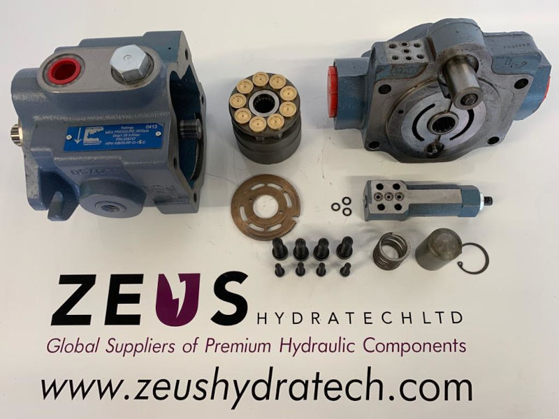
Above: a deconstructed Piston pump
A positive-displacement pump displaces the same amount of liquid for each rotation of the rotary pumping element. As the pump turns, fluid is displaced from an area of increasing volume to an area of decreasing volume. Close tolerance fits between the pumping element and the pump case permit negligible amounts of working fluid to slip past the pumping element when compared to the theoretical maximum delivery. These close tolerances allow for the pump to be self-priming; to have the ability to use the liquid stored in its housing to generate a vacuum on the inlet, or suction, line. The high tolerances of the pump components allow for the pump to be used in high pressure hydraulic applications.
Positive displacement pumps can take the form of either fixed displacement or variable displacement pumps. To achieve variable displacement, the geometry of this displacement chamber must be changed.
In a non-positive displacement pump the rate of flow from the pump, changes as the restriction on the pump outlet is changed. In other words, if the pressure at the pump outlet is decreased, the flow rate will increase, and vice versa. A non-positive displacement pump can adjust the flow rate according to the pressure at the outlet of the pump is because of the slippage. The slippage is desirable in circulation pump systems because it helps the system to avoid rising the system pressure to dangerous levels and helps to save energy required by the prime mover i.e. engine or motor.

Above: A piston pump with a load sense compensation control
In an industrial hydraulic system, three main types of pump are used:
View our range of Hydraulic Gear Pumps here.
This variation of pump is strictly a fixed-displacement component. Gear pumps transport fluid by using the motion of spinning cogs or gears. The revolving element provides suction at the pump inlet and forms a liquid seal with the pump casing. The pump's spinning gear chambers contain the fluid brought into the device and transport it to the discharge. The two fundamental types of gear pumps are exterior and internal.
The internal gear pump is more expensive than the external gear pump but is more robust and significantly quieter. There is a much smoother output, and they can run at higher pressures without the excessive noise levels.
An external gear pump is made up of two interchangeable, identical gears that are supported by independent shafts. Typically, a motor drives one of the gears while a gear drives the other (the idler). In some circumstances, motors may be used to drive both shafts. On either side of the casing, there are bearings that support the shafts. On the pump's input side, the gears expand the volume as they separate from the mesh. As the gears continue to revolve in opposition to the pump casing, liquid flows into the cavities and is caught by the gear teeth.
Around the casing, the trapped fluid is transferred from the intake to the outlet. The volume is lowered and the fluid is forced out under pressure as the gear teeth on the pump's outlet side become interlocked.
Because the gears are interlocked with a very tight tolerance fit, no fluid is transported back through the centre between them. The pump can create a vacuum at the intake and prevent fluid from flowing back from the outlet side thanks to the close tolerances between the gears and the pump casing (although, with low viscosity fluids, leakage is more likely).
The external gear pump is the cheapest type of hydraulic pump and is very popular on systems which are constrained to have a very low build cost. Noise levels on external gear pumps are generally high and efficiency is typically low – both get worse as the pressure increases however, for low pressure intermittent use, these pumps are perfectly adequate.
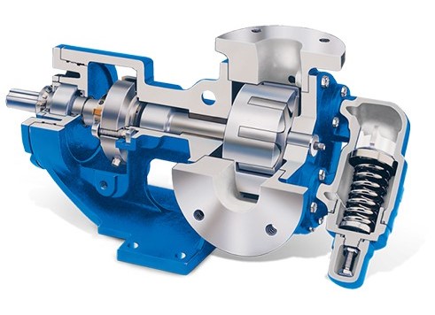
Above: An internal view of an internal gear pump
View our range of Hydraulic Vane Pumps here.
Vane pumps can be configured for variable or fixed displacement. A vane pump uses a rotating, slotted cylinder (or rotor) that contains several rotating vanes. Due to an offset in the casing bore, the vanes slide in and out as the rotor turns. As a result of this action, the volume increases and decreases, forcing liquid through the pump. By applying outlet pressure to the underside of each vane element, the vanes are forced up against the cam ring. The vanes exert more pressure as the output pressure rises to minimise internal leakage. If the pressure builds up too much on the pump's suction side, an excessively high vane tip force develops which would cause wear or damage. More sophisticated versions of this pump limit the vane tip force by various means.
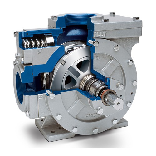
Above: An internal view of a vane pump
This pump, which is employed in both industrial and mobile applications, can be serviced extremely easily (or even have its displacement changed) by only switching out the internal pumping cartridge. When performing this procedure, it is crucial to check the condition of the drive shaft splines and clear away any worn debris from the pump's casing before replacing the cartridge. The front bearing and shaft seal still need to be replaced, which necessitates removing the pump from the prime mover in order to change the front bearing and the shaft seal.
Pressure compensated vane pumps are a variation of a vane pump which can provide pressure only when necessary, offer a higher level of efficiency compared to fixed Displacement balanced vane pumps. Due to the downstream flow resistance, the pump pressure will finally generate enough force to move the internal compensator spool as it rises (known as cracking pressure). Pump displacement will decrease as pressure increases, finally moving to a de-stroke state. At this point, it will maintain its own internal lubrication and leakage into the pump casing by remaining slightly on stroke.
Vane pumps are most effective in applications requiring lower viscosities of fluids, such as those involving gas (propane), ammonia, solvents, fuel oils, alcohol, and so forth. Vane pumps can operate at maximum efficiency with these non-lubricating liquids since they have no internal metal-to-metal contact and self-compensate for wear.
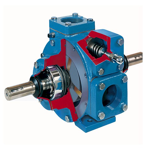
Above: An internal view of a pressure compensated vane pump
View our range of Hydraulic Piston Pumps here.
A typical example of a variable displacement pump is a piston pump, which allows for the control of fluid displacement per revolution while maintaining a constant RPM. Pumps like this work effectively in circuits that require variable speed or reversibility.
The arrangement of the pistons in a piston pump can be either radial or axial. Axial piston pumps are available in a wide range of displacements and pressure capabilities that make them suited for many mobile and industrial activities, whereas radial variants tend to be specialised for applications requiring very high power.
An angled swash plate powered by the input shaft drives a set of pistons that are housed inside a cylinder block to create axial-piston pumps. The pistons reciprocate in their respective cylinder block bores as the swash plate rotates, producing the pumping action. There are two options for axial-piston pumps: ones with the input shaft and pistons placed at an angle to the piston bores - these are sometimes referred to as bent axis pumps. Technically speaking, bent axis pumps are often slightly more volumetrically efficient, but they also tend to be a little bit bigger for a given capacity and their design can cause packing issues in some applications. A piston-type pump's ability to vary displacement by merely adjusting the swash plate's angle is one of its special features. With relatively straightforward actuators, any displacement between zero and maximum can be easily produced.

Above: An internal view of a piston pump
In a hydraulic system, the number one reason for a loss in component performance or reliability is a contamination of the working fluid. A contamination in a hydraulic system can cause blockages and restrictions within the system which can impede the fluid flow which will negatively impact the system performance. As well as this, wear and tear and even corrosion can occur which can cause abrasions and other damage to the system components which will, in the long term, lead to increased maintenance and replacement costs. Contaminants also cause a reduction in the lubrication of the working fluid, which increases the wear and friction acting on components. The thermal conductivity of working fluid can be affected as well, which will hinder the ability of the fluid to transfer heat. The problems caused by system contamination should not be understated due to their wide-ranging effects on a hydraulic system. In order to ensure the continued performance and increase the reliability of a pump, regular cleaning processes should be carried out.
Not all hydraulic pumps are affected equally, however. For example, a piston pump deals very poorly with contaminants. The close tolerances of the piston pump mean that even slight contamination of the working fluid can create very severe obstructions and blockages within the pump. Compare this to a gear pump however, and the gear pump has less strict tolerances, which allow more slippage to occur in the pump. This means that the gear pump can maintain performance with more contaminated working fluid than a piston pump as the pump components are less affected by contaminants in the system. A vane pump performs somewhere between the performance of the gear pump and the piston pump due to its design.
The piston pump is the most sophisticated of the three pump designs, with very close tolerances and the ability to perform at the highest pressure. The vane pump design is not as advanced or efficient as a piston pump, but it is slightly more tolerant of contaminants. Finally, the gear pump has the least strict tolerances and operates at the lowest pressures, making it the most tolerant of contaminants.
Routine maintenance methods include:
Checking the filters and strainers - a dirty or blocked filter or strainer will generate a build-up of pressure inside of the pump. Regular maintenance of these elements will ensure that the pump continues to flow at capacity.
Monitoring the pressure sensing equipment - checking the pressure sensors will allow you to ensure the system is performing its best, and safely. Pressure sensors can help you detect leaks, blockages or other issues within the system that wouldn't be immediately apparent that affect performance.
Look for cracks or collapsed piping/hoses that will disrupt the system - cracks can cause a loss of fluid pressure or fluid level in a system and potentially lead to air being introduced to a system which can cause damage to components. If a pipe is collapsed in a high pressure region of the system, components can be worn by the resultant stress, leading to damage of the components.
If you are interested in finding out more about oil contamination and methods of dealing with it, click here.
Vat Reg Number: 846644204 Company Registration Number: 5230249
© Copyright 2025 Zeus Hydratech | All Rights Reserved